Six Degree-of-Freedom Submicron Positioning Stage
(2021)
Precision fine motion stage (FMS) concept developed to meet the requirements of a specific photolithography process for the manufacturing of IC chips. The application required 6 DoF control and submicron repeatability across a range of motion that spans ±0.1mm in x and y, ±1.5mm in z, ±1 mrad in θx and θy, and ±52 mrad in θz. This work was completed for my Master's thesis, which you can read here.
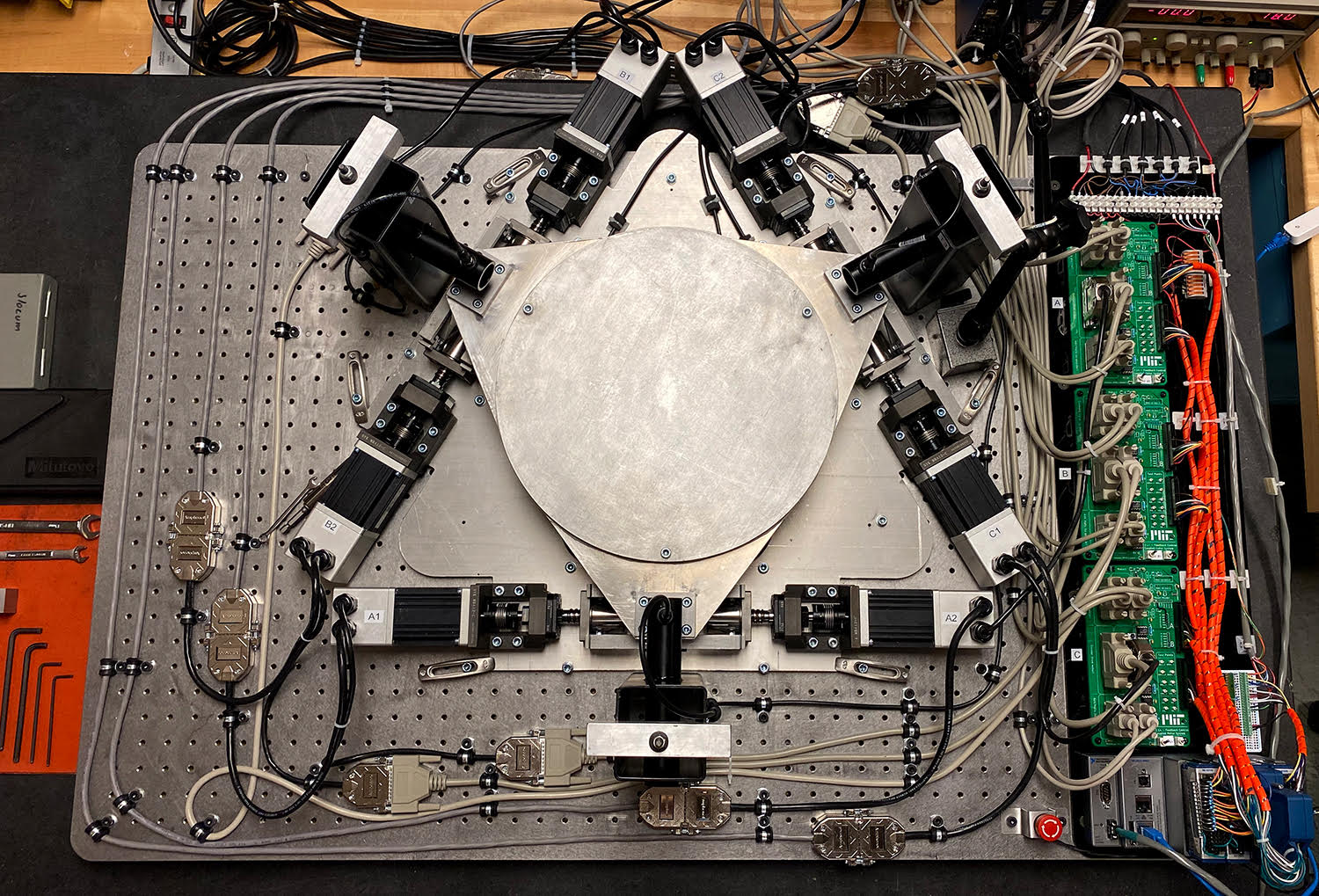 This proof-of-concept prototype was built as rig to evaluate the kinematics, repeatability, and dynamic performance of a concept machine that uses flexures paired with precision ballscrews and BLDC motors to achieve 6 DoF motion.
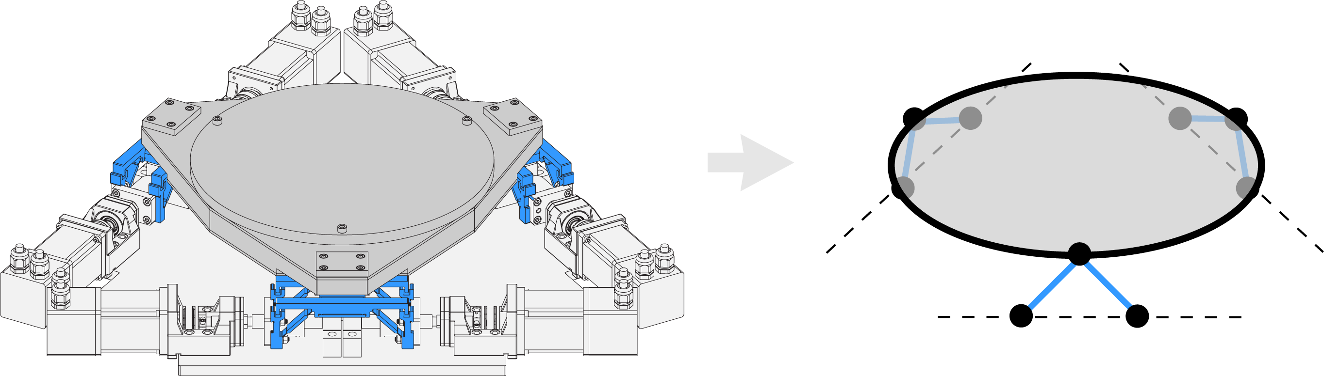 The stage is designed as an ‘exactly-constrained’ system and can be simplified as a platform supported by 3 pairs of struts. This parallel configuration is similar to a Stewart platform, although in this case the strut lengths remain constant and motion is instead created by moving the end points of the struts.
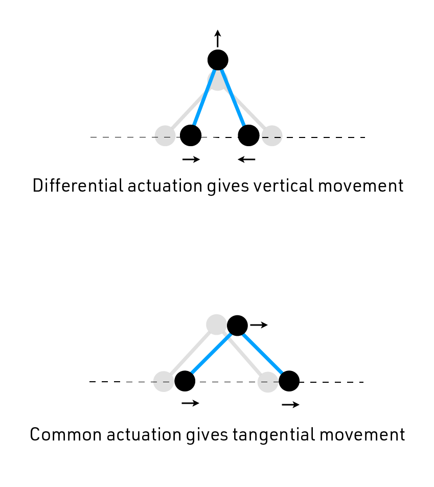 The lower nodes of each pair of struts can move along a single axis to create motion at the upper node, which is connected to the platform. Each pair of struts can thus work together to create vertical and tangential motions at their connection point to the platform.
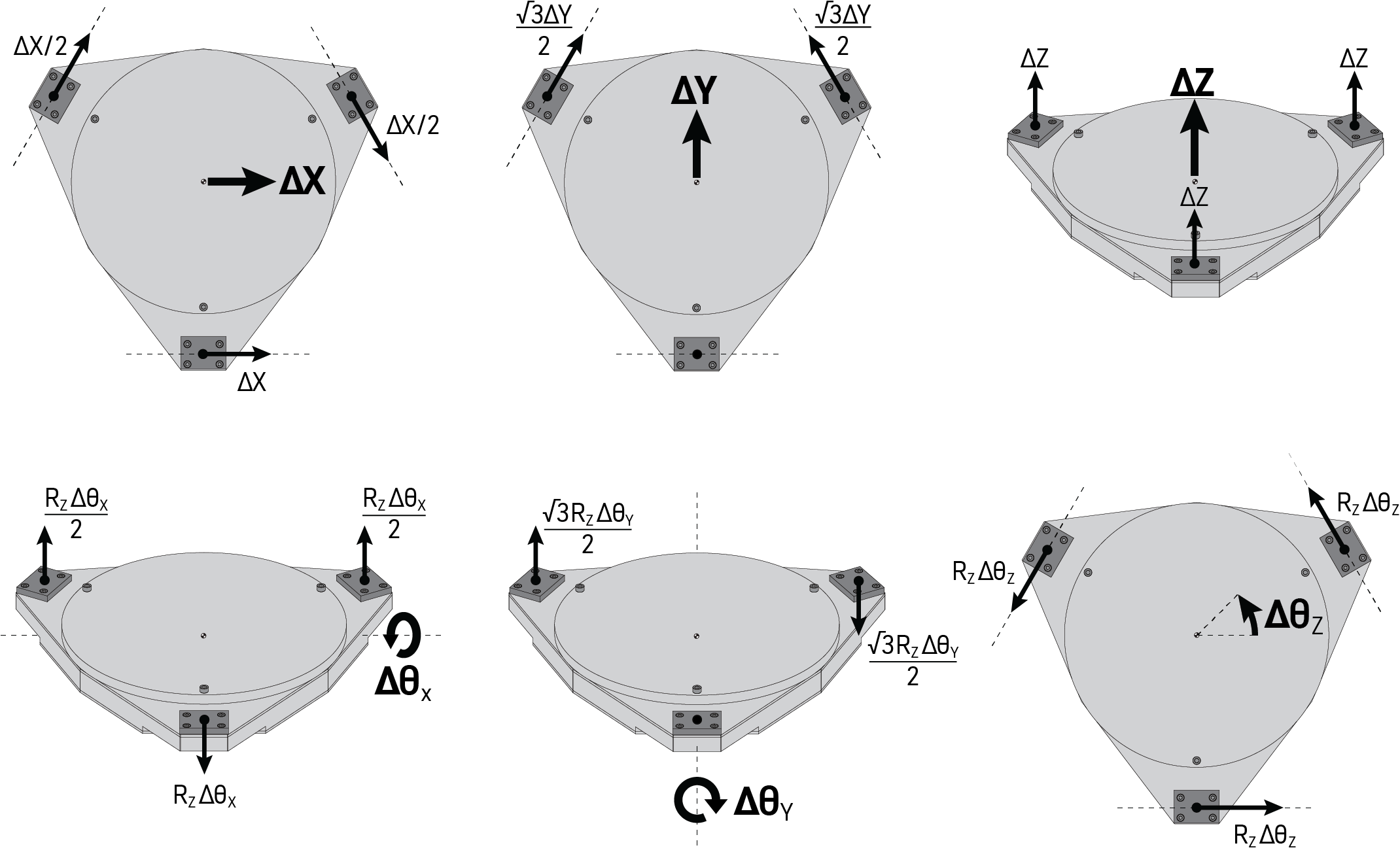 By prescribing vertical or tangential motion at each of the three connection points on the platform we can control the stage in all six degrees-of-freedom. Because the range of motion of the angular degrees-of-freedom is so small, these inputs can be linearly combined to create any desired motion profile.
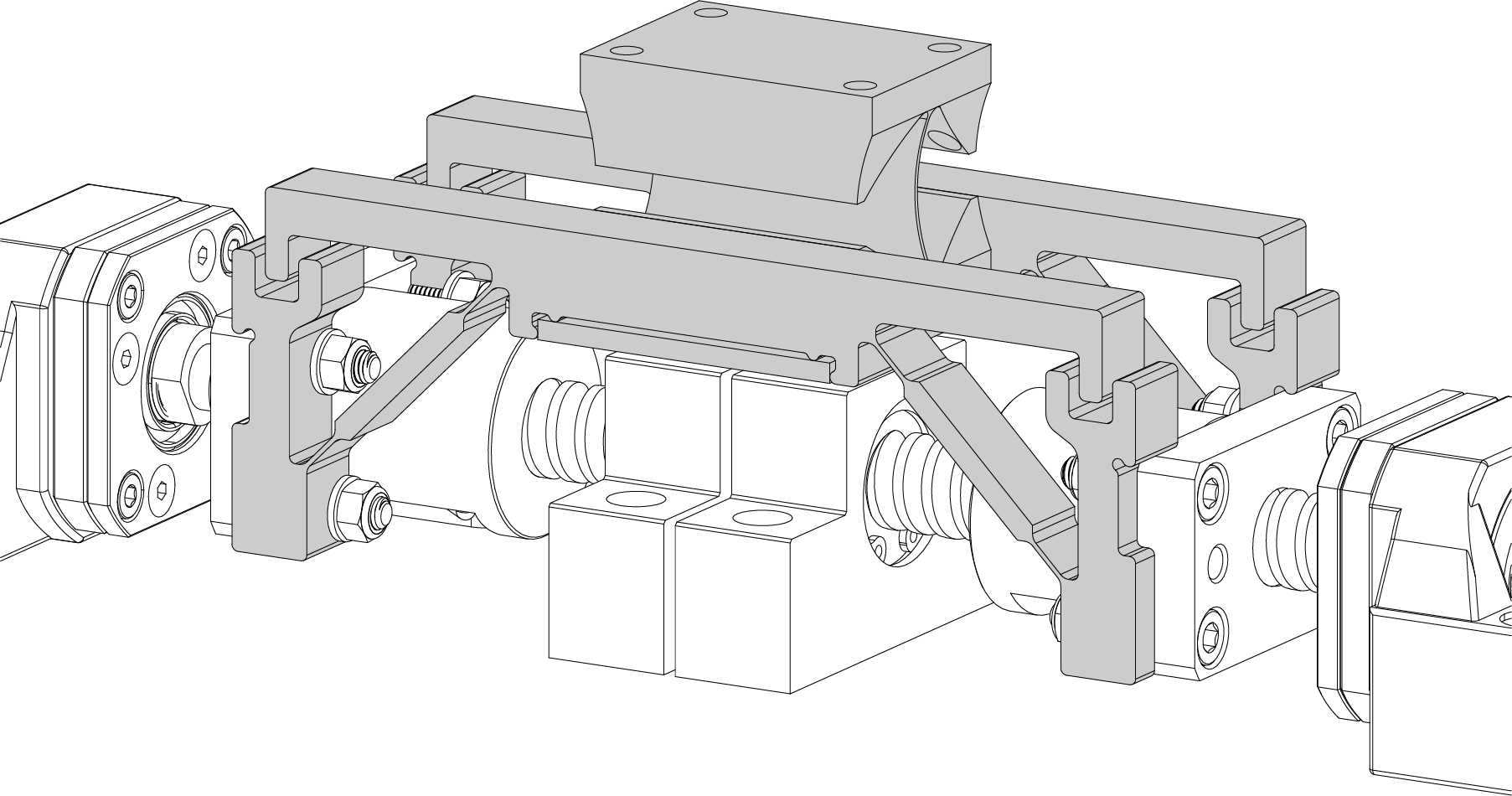 The struts are created from a flexure assembly to create a backlash free and zero wear joint between the actuators and the stage platform. The ends of the struts ride on precision ballscrews that are preloaded and have gothic-arch profiles for maximum repeatability and stiffness.
FEA simulation of differential mode inputs producing vertical motion at the output.
FEA simulation of V flexures and blade flexure deflecting through their full operating range. Each flexure is designed for a 10 million cycle fatigue life in 7075 aluminum or an infinite fatigue life in steel. The proof-of-concept prototype features aluminum flexures to reduce fabrication costs, but a production set of steel flexures could be swapped in with minimal changes to the mechanical design of the machine.
Video of pure Z motion on the stage. The black post structure above the platform is a sensor that is measuring the vertical displacement directly above the actuation point.
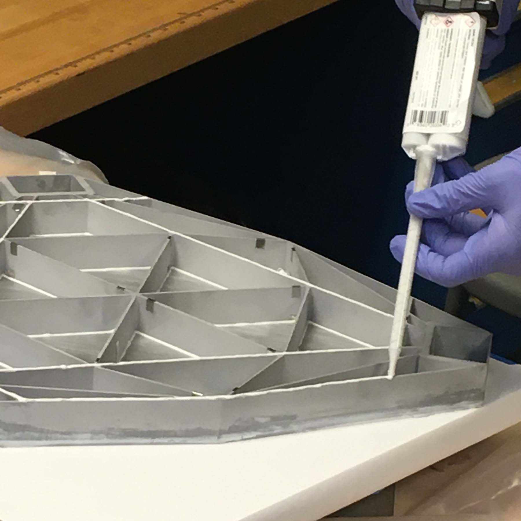
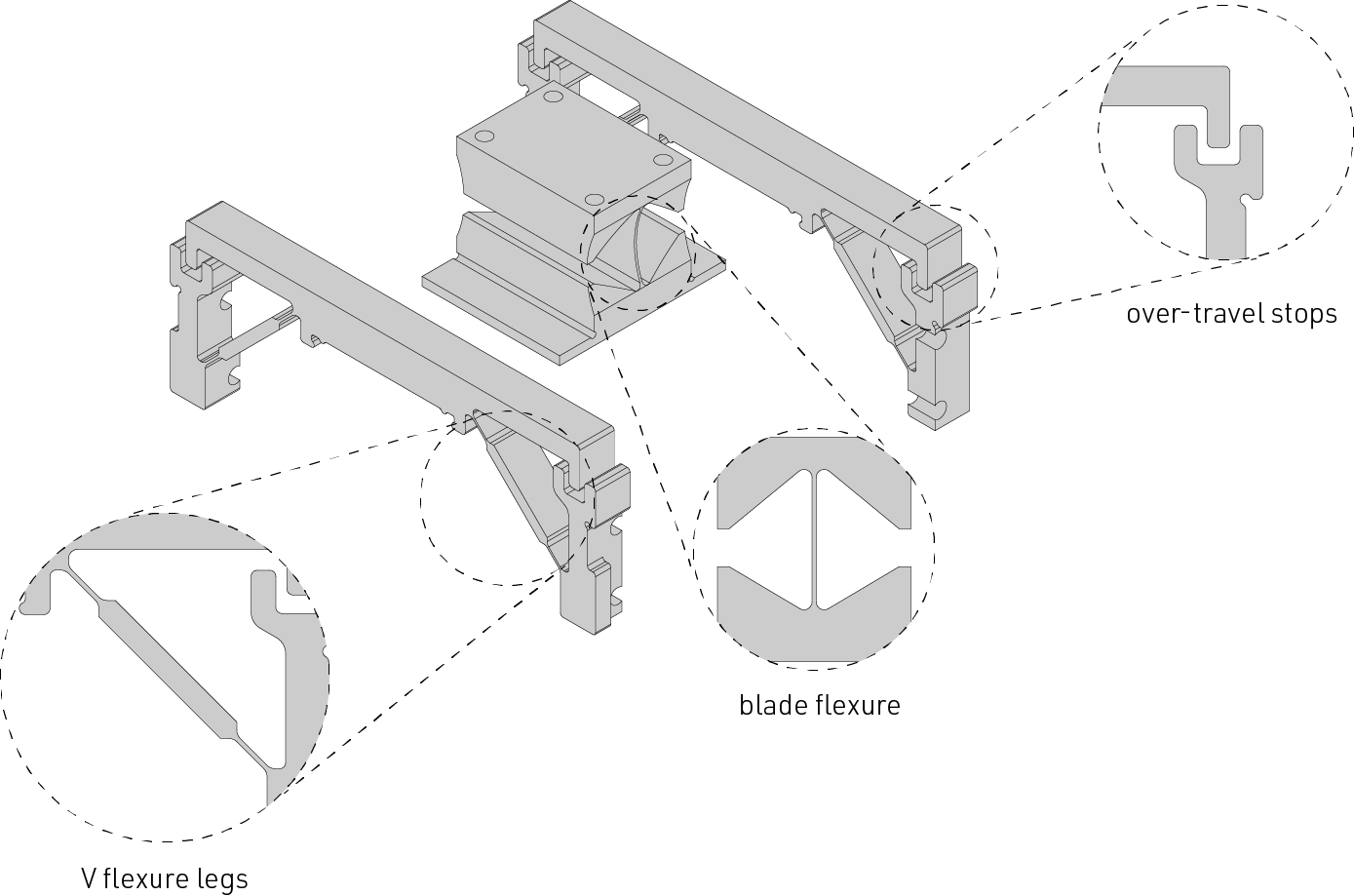 The flexure set is assembled from 3 pieces which includes a blade flexure for decoupling twisting motions and two V flexures. The entire assembly is bonded together with structural adhesive for the best shear transfer between elements.
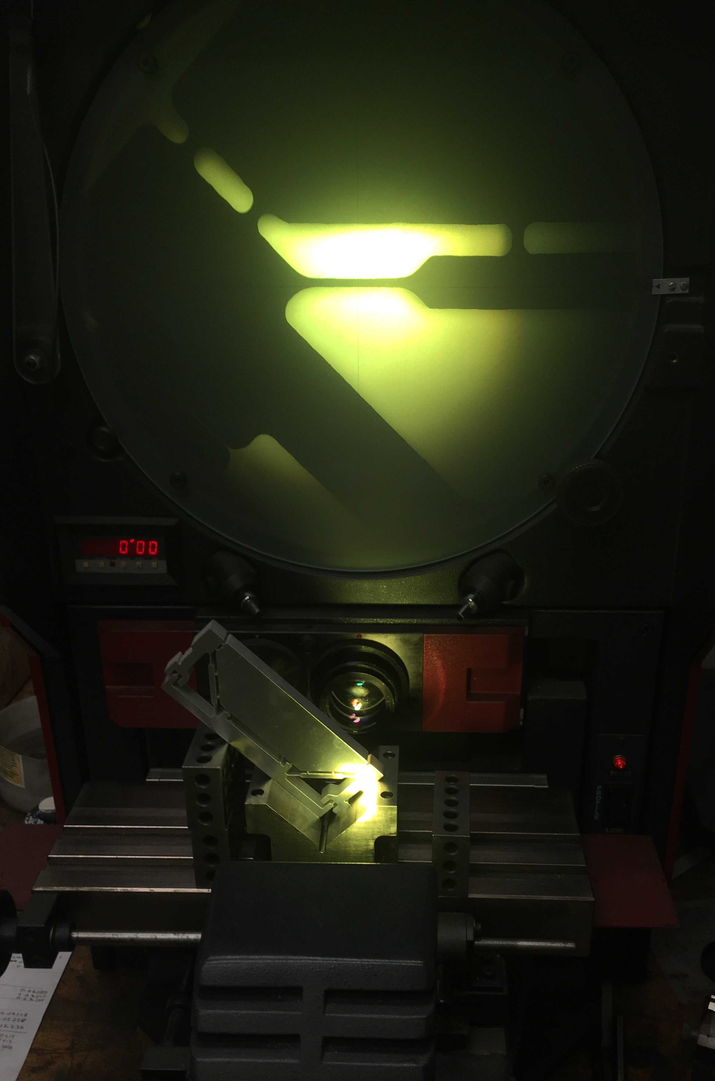 After getting flexures back from fabricators, critical dimensions in hard to reach places were inspected using an optical comparator.
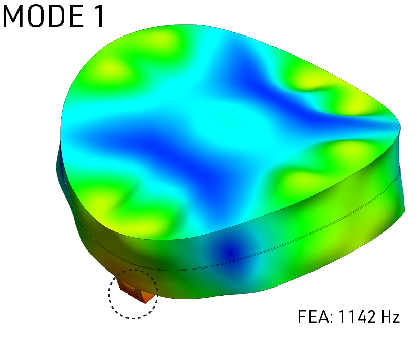
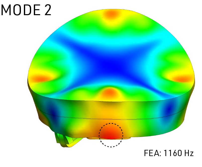
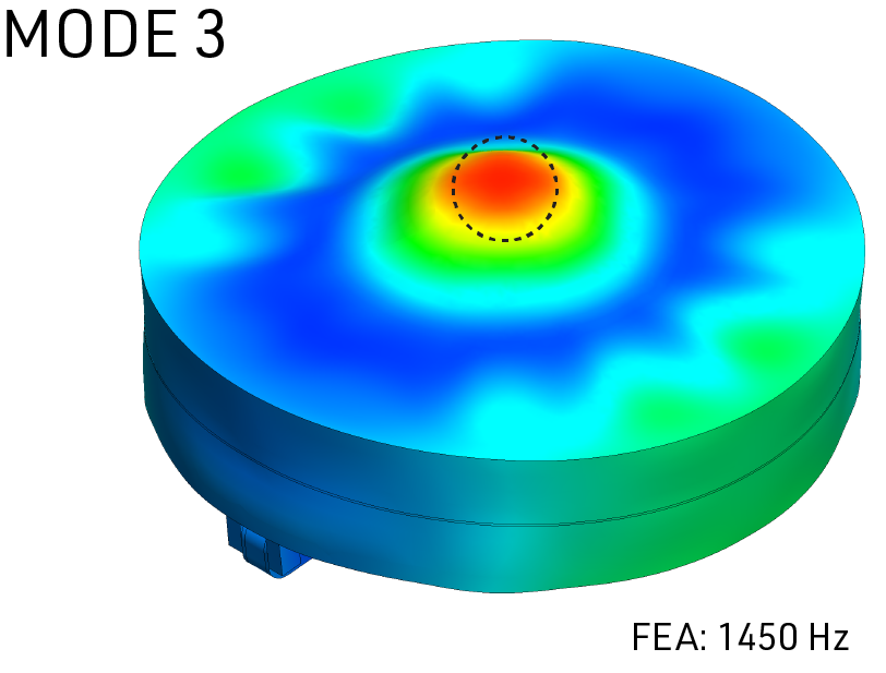
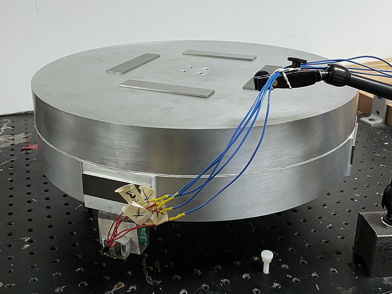
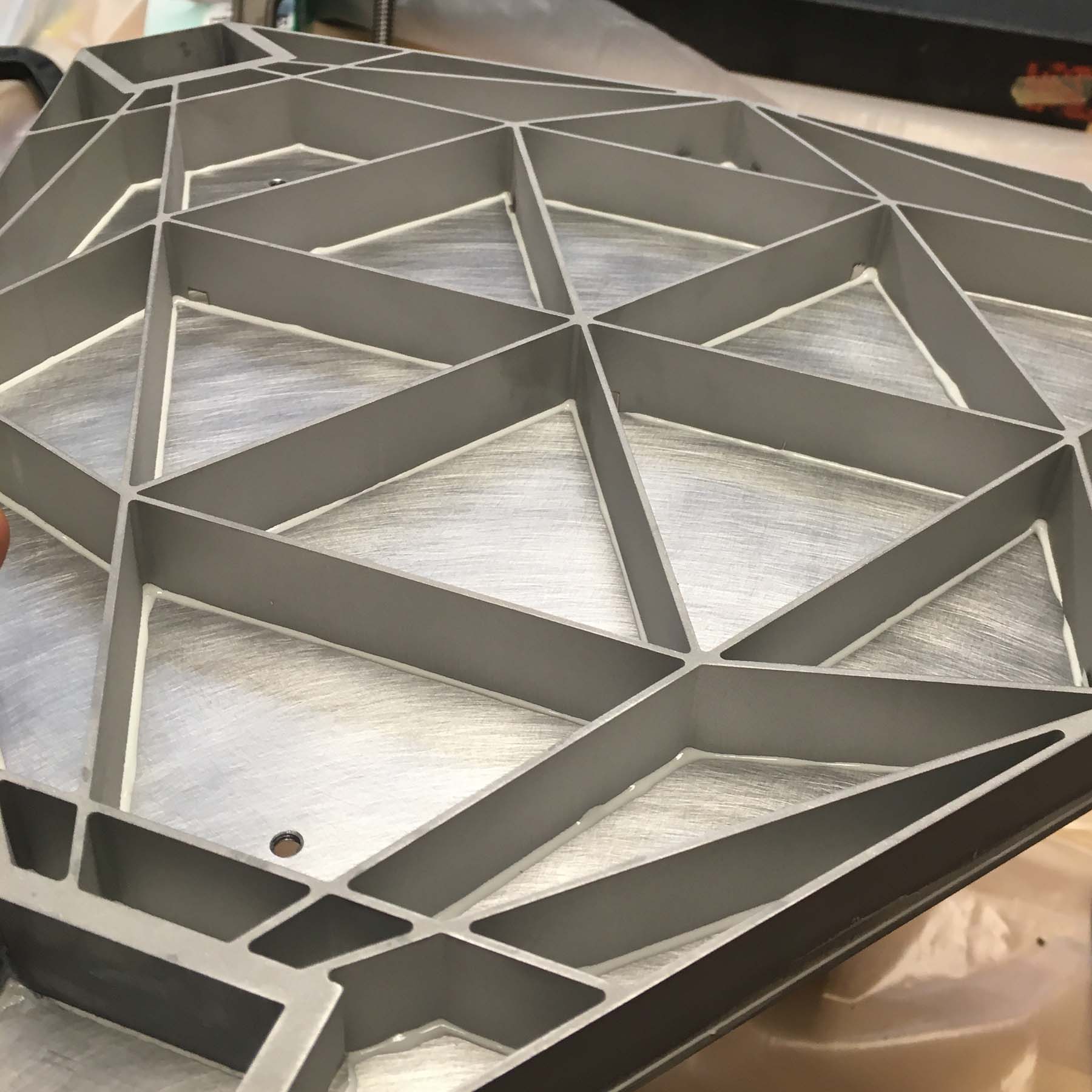
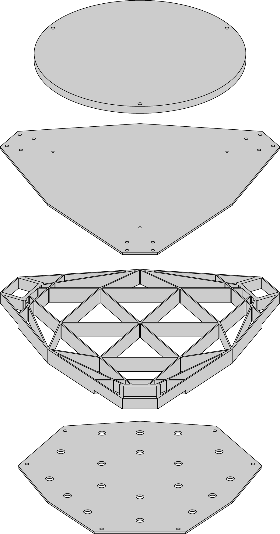 Maintaining a high stiffness to weight ratio is important for keeping the resonant modes of the platform structure high. To achieve this functional requirement, the stage platform is fabricated as a sandwich panel using a lightweight aluminum isogrid core bonded to 1.5 mm thick face sheets on either side. A 3 kg disc is bolted to the top of the platform to simulate the weight of a vacuum chuck that would be installed during typical use.
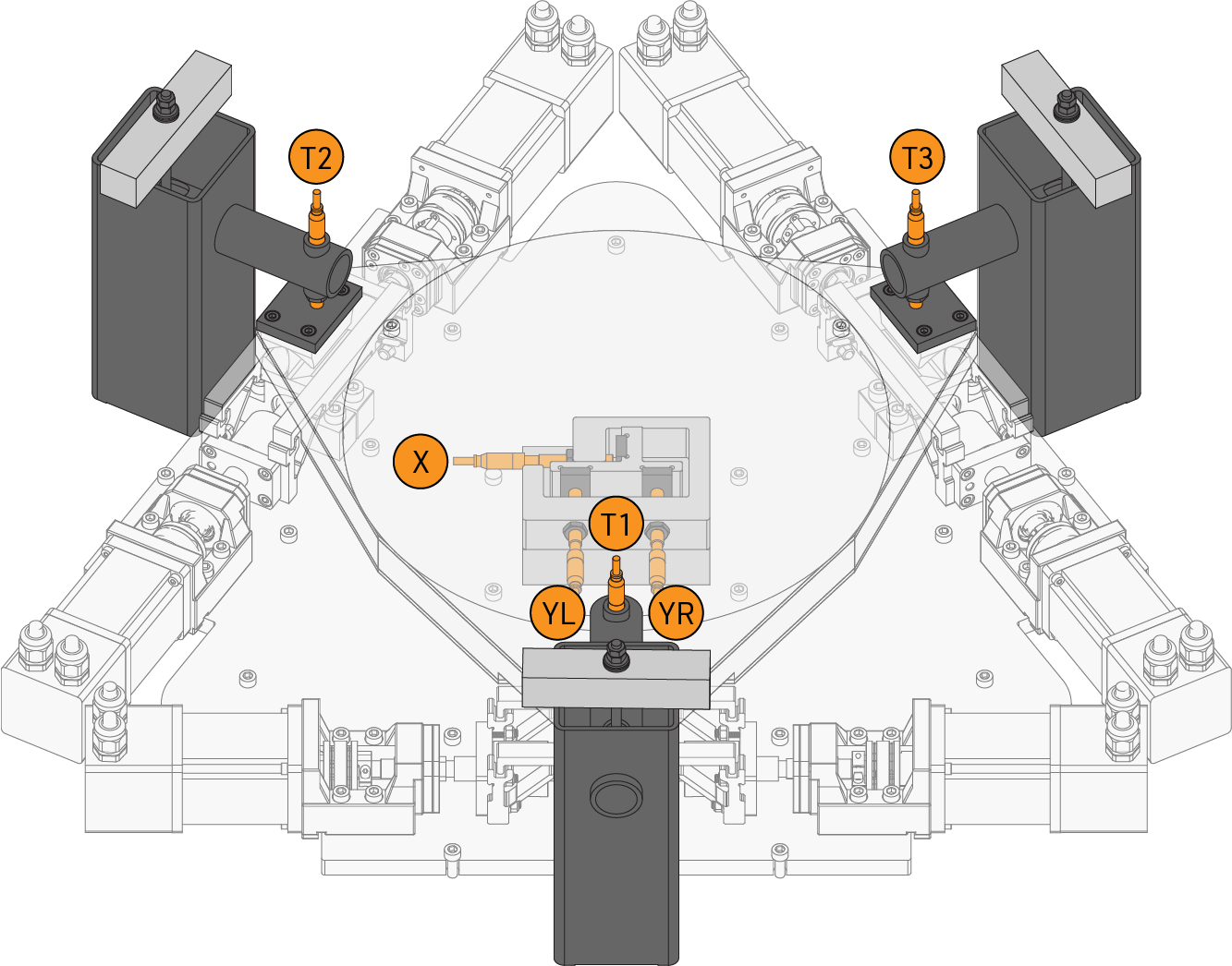 A collection of six sensors work together to give estimates of the stage pose in all six degrees-of-freedom.
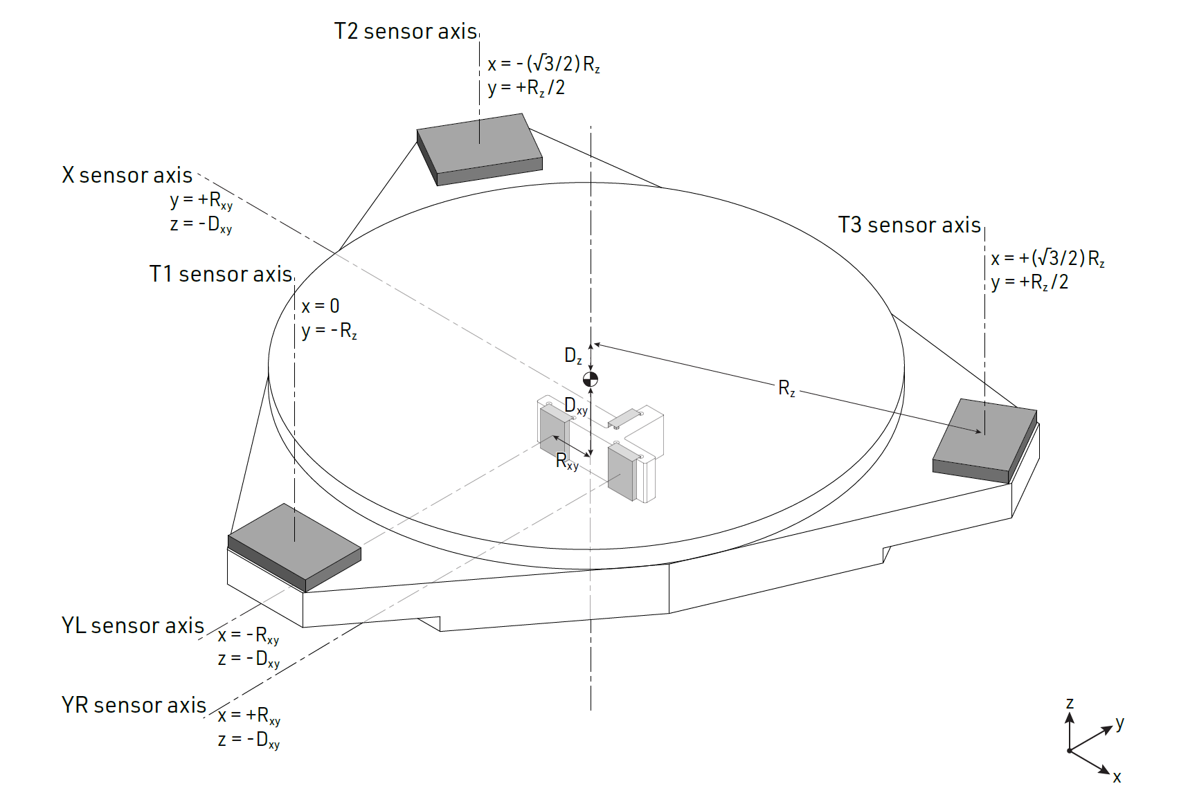 Diagram of the sensing points and sensor axes on the stage. The coordinates of the sensor axes are given with respect to the center of mass of the platform which was designed to coincide with the center of stiffness of the structure.
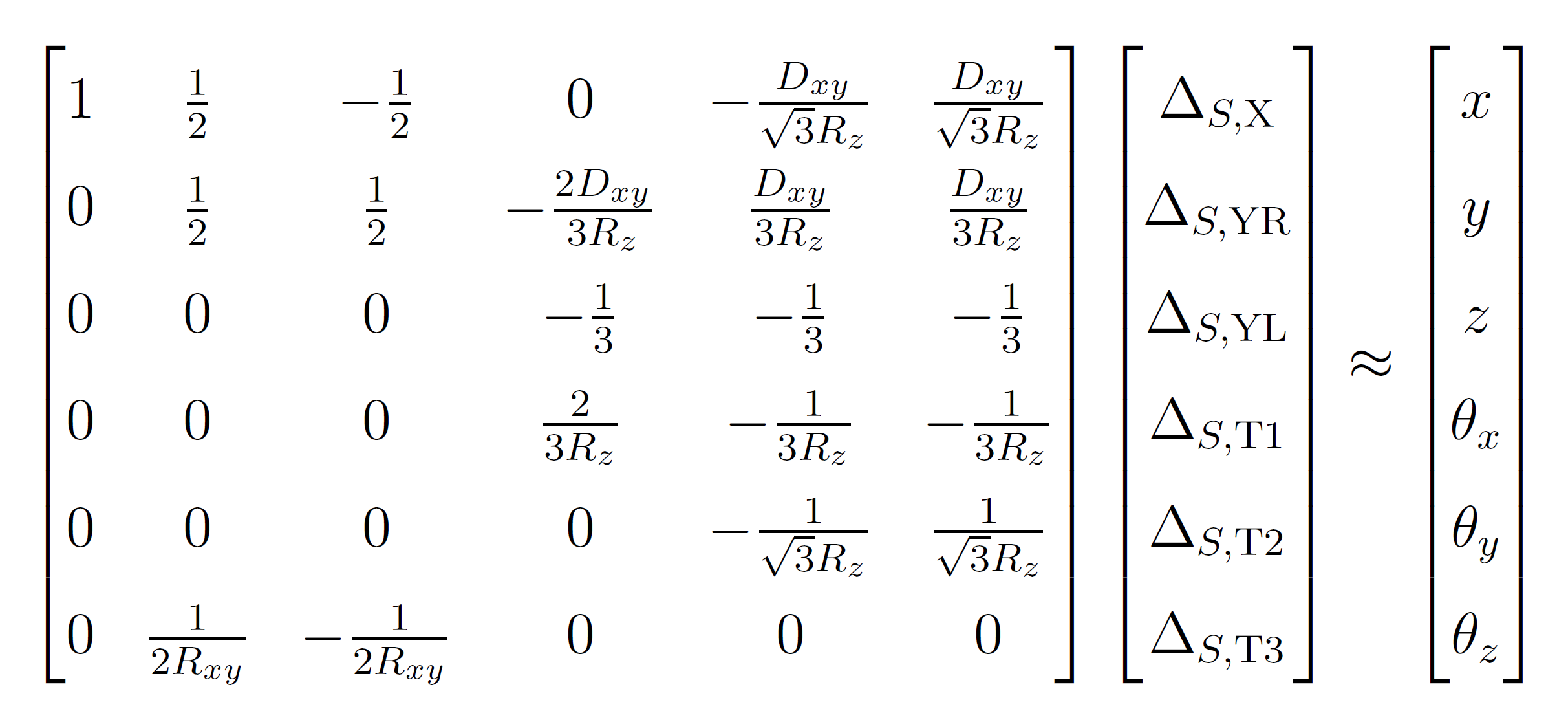 A first order system of equations is used to decouple sensor readings and estimate the stage pose. Although higher order models could be used for better accuracy, the low computational expense of this linear system is perfect for taking real-time measurements of the dynamic behavior of the stage.
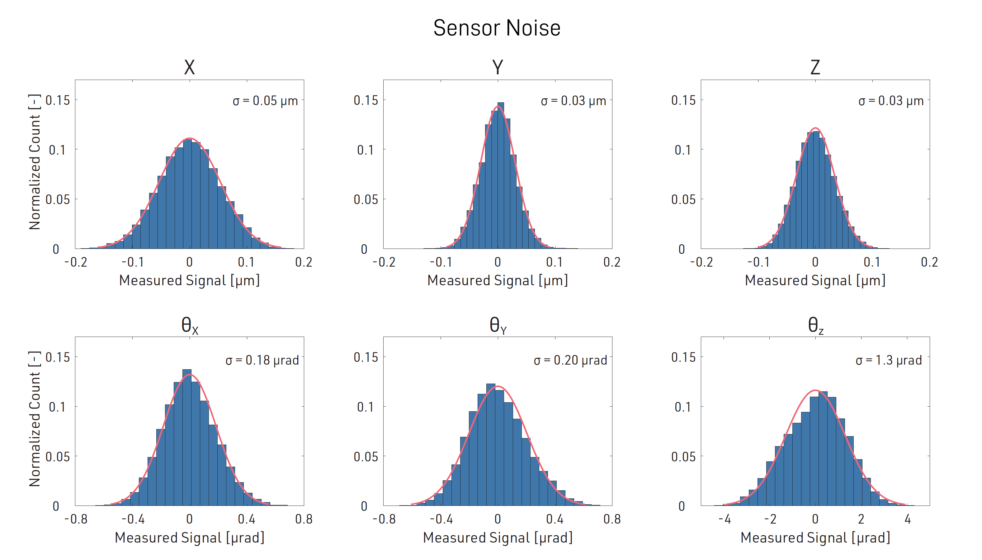 The sensors used in the metrology system are industrial non-contact inductive sensors. Compared to high precision capacitive sensors, the inductive sensors offered a larger measurement range and lower cost in a more robust package. A combination of signal conditioning and signal processing brought the RMS noise of the inexpensive inductive sensors down by an order of magnitude to the sub-micron range.
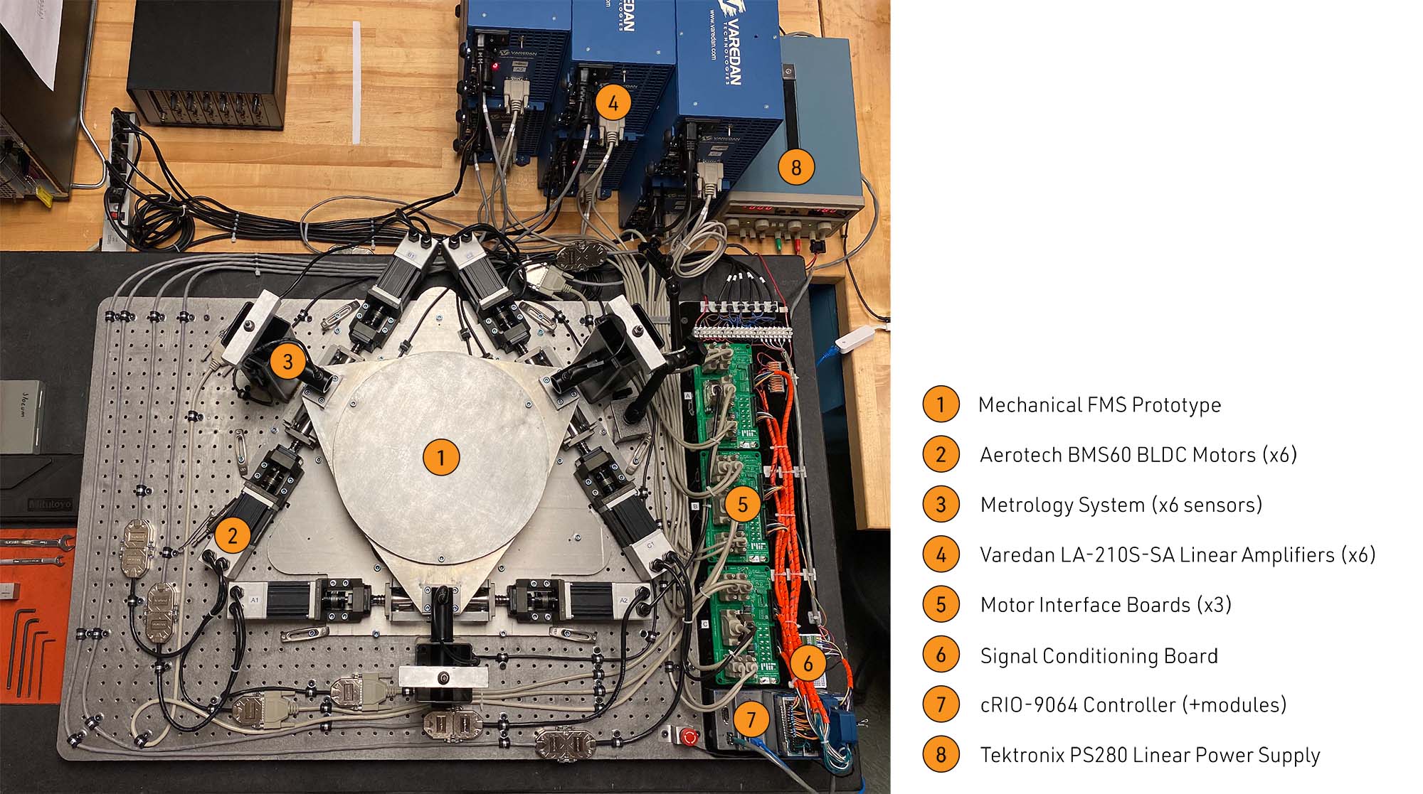 Mechanical and electronic components work together to run the prototype system. In order to keep electrical noise down to a minimum, linear amplifiers are used along with properly grounded and shielded cables and twisted pair wiring where appropriate.
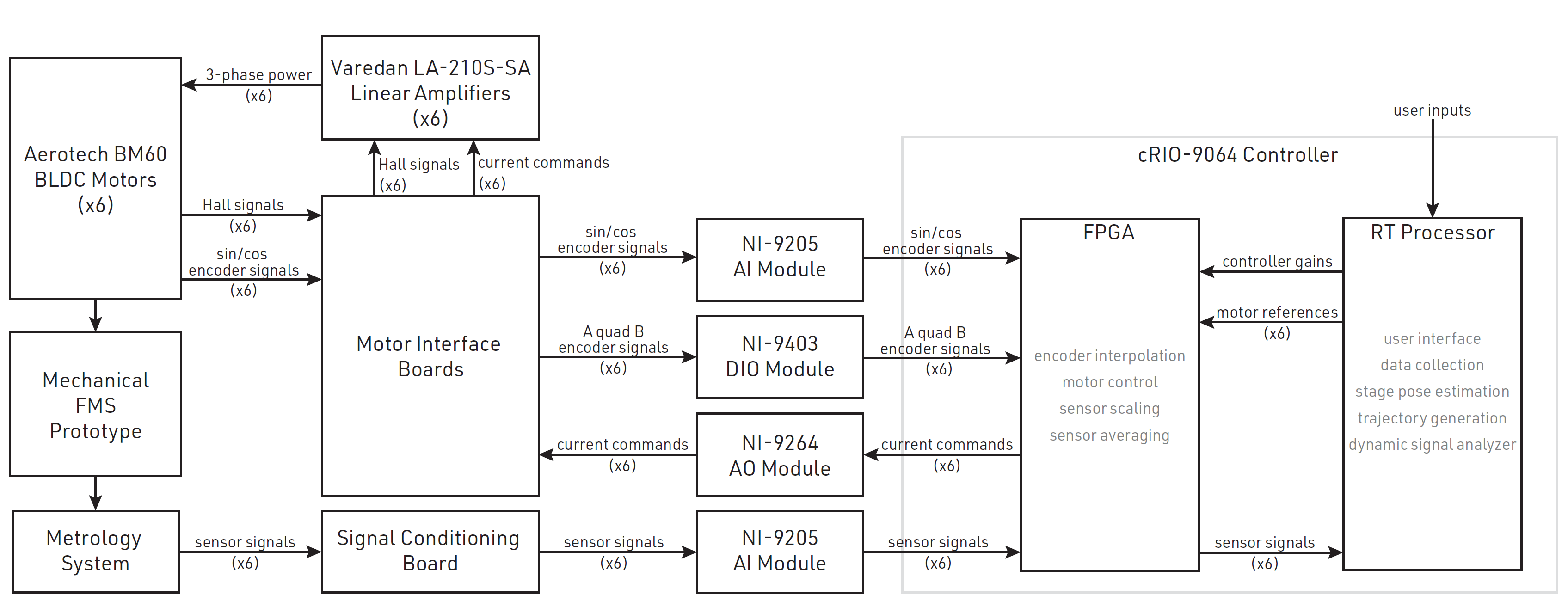 System block diagram showing interactions between each element. Custom motor interface boards route power and encoder signals between the motors, encoders, amplifiers, and controller. The controller features a real time processor as well as an FPGA module for high speed signal processing and motor control.
Video of the stage processing through its full ±52 mrad θz motion.
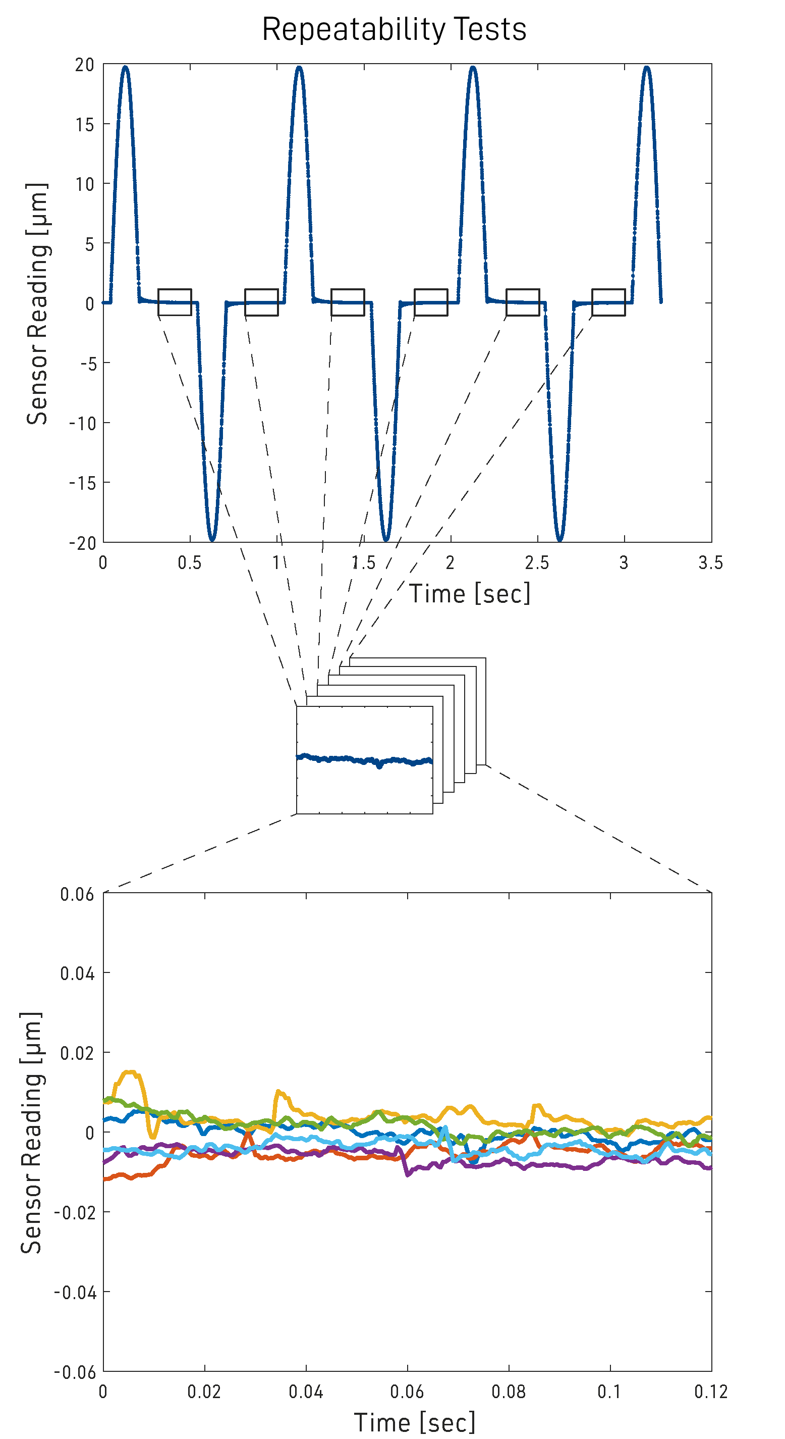 The repeatability of each DoF was quantified using a bidirectional motion profile. Approaching the ‘zero’ point from two directions captures any effects caused by backlash or other nonlinear behavior.
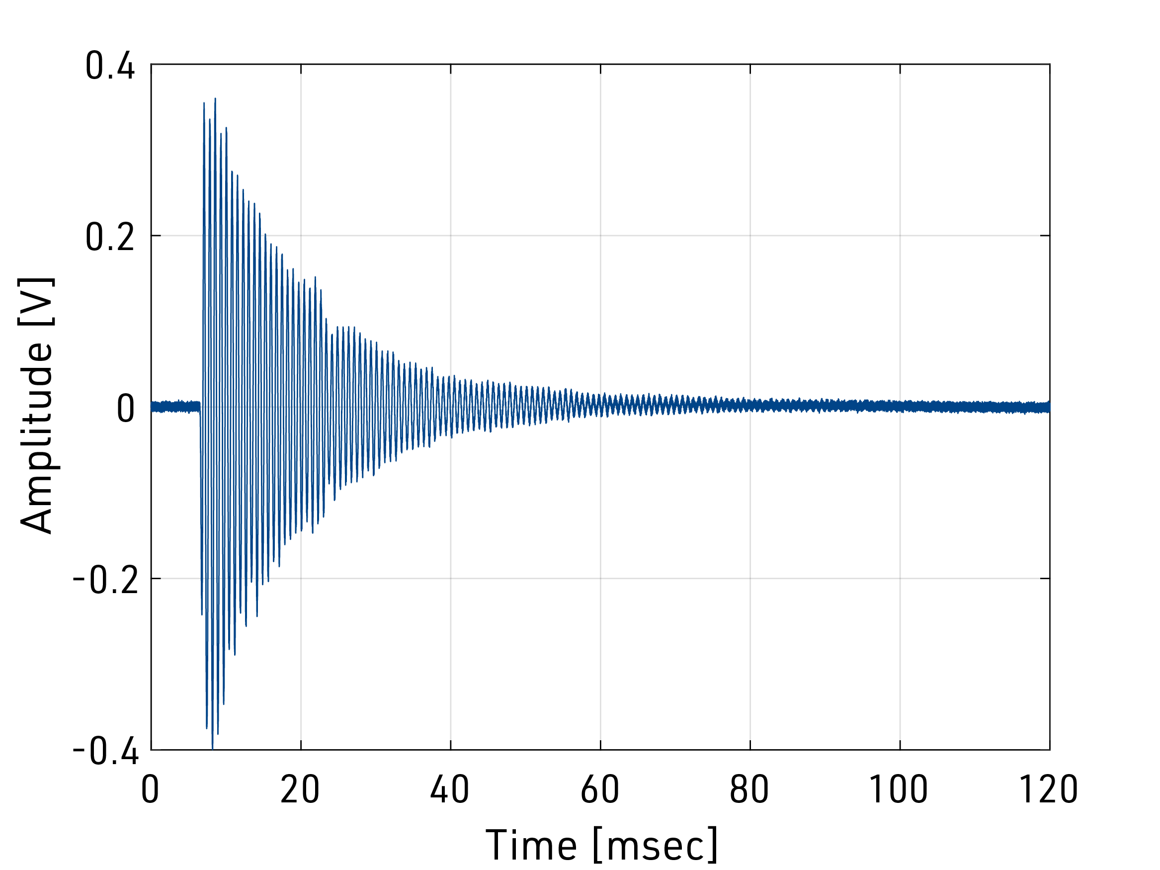
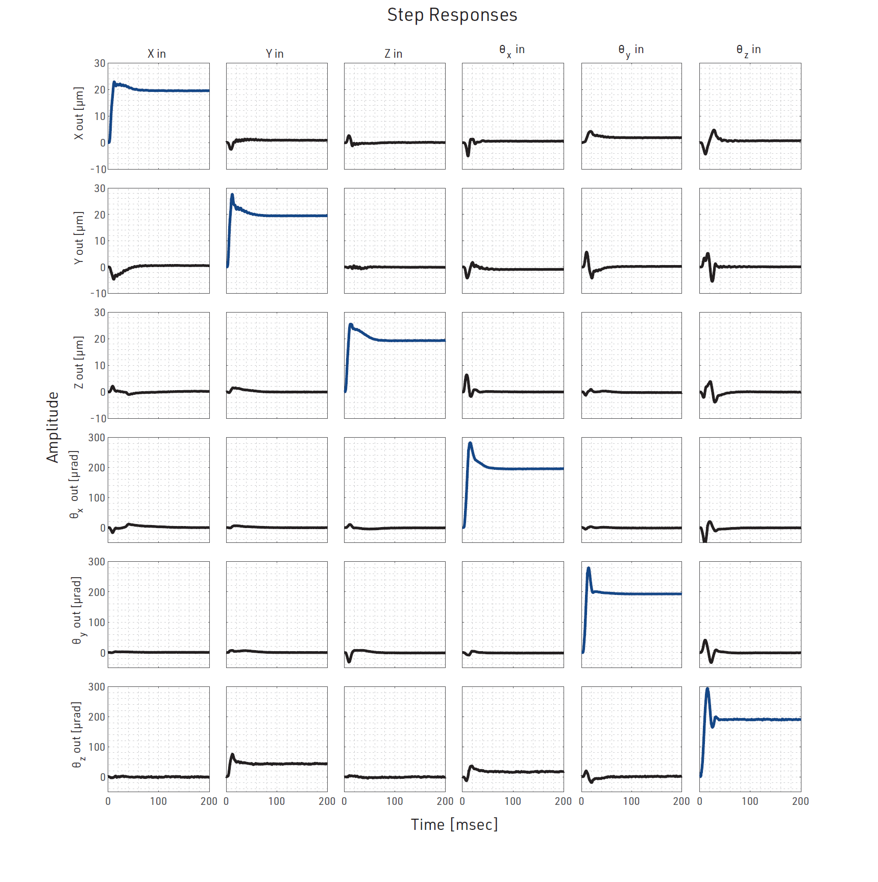 A 6x6 matrix of step responses shows any open loop cross-coupling that occurs while the stage is moving in each of its degrees-of-freedom. The columns of the matrix represent a commanded step in each degree-of-freedom, while the rows show the measured output. A perfectly decoupled system would show step responses along the main diagonal of the matrix and flat lines everywhere else. While we do see some transient coupling between DoFs, most signals settle back down to zero, which is perfectly acceptable for a ‘step and expose’ type machine.
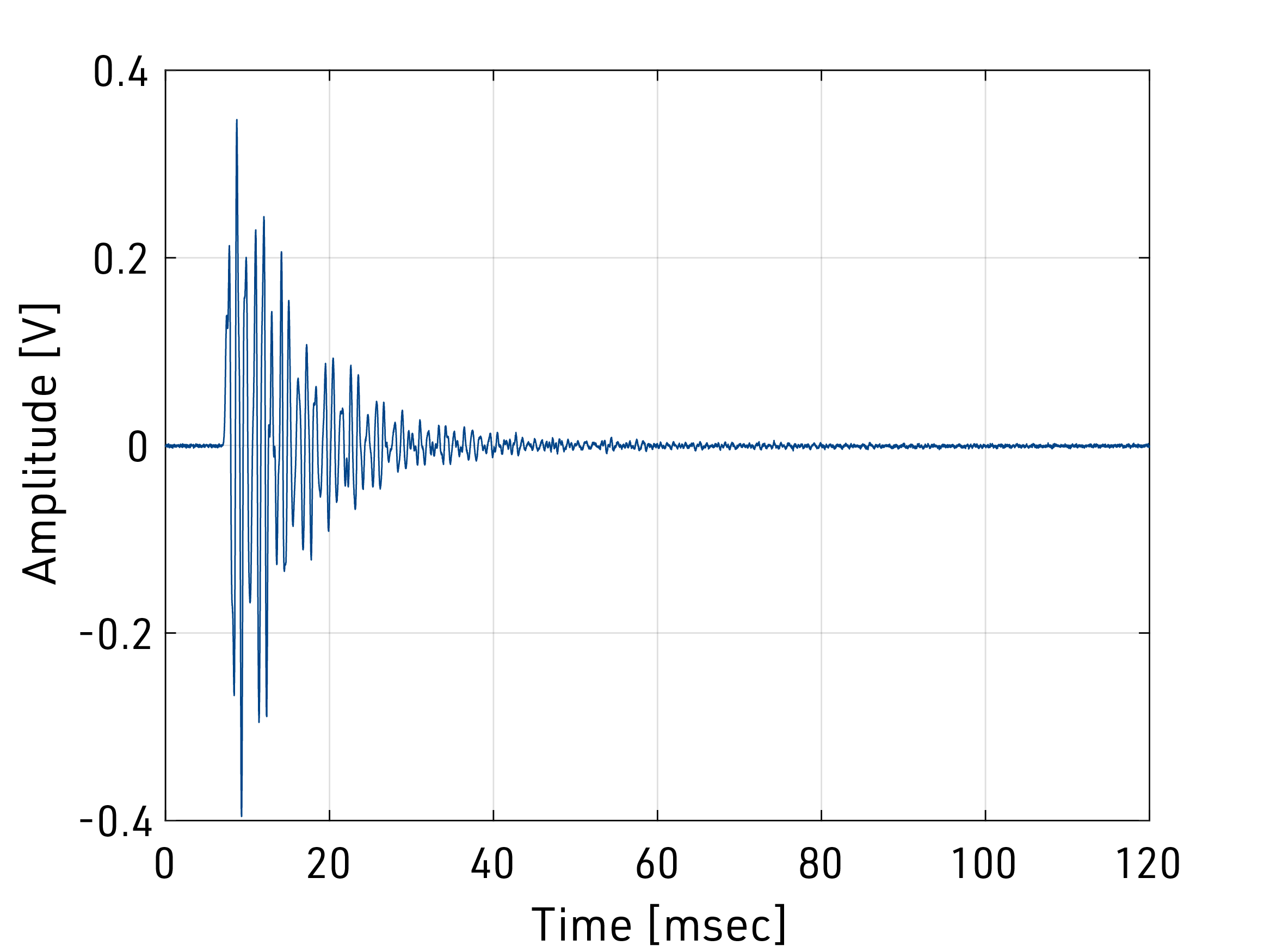
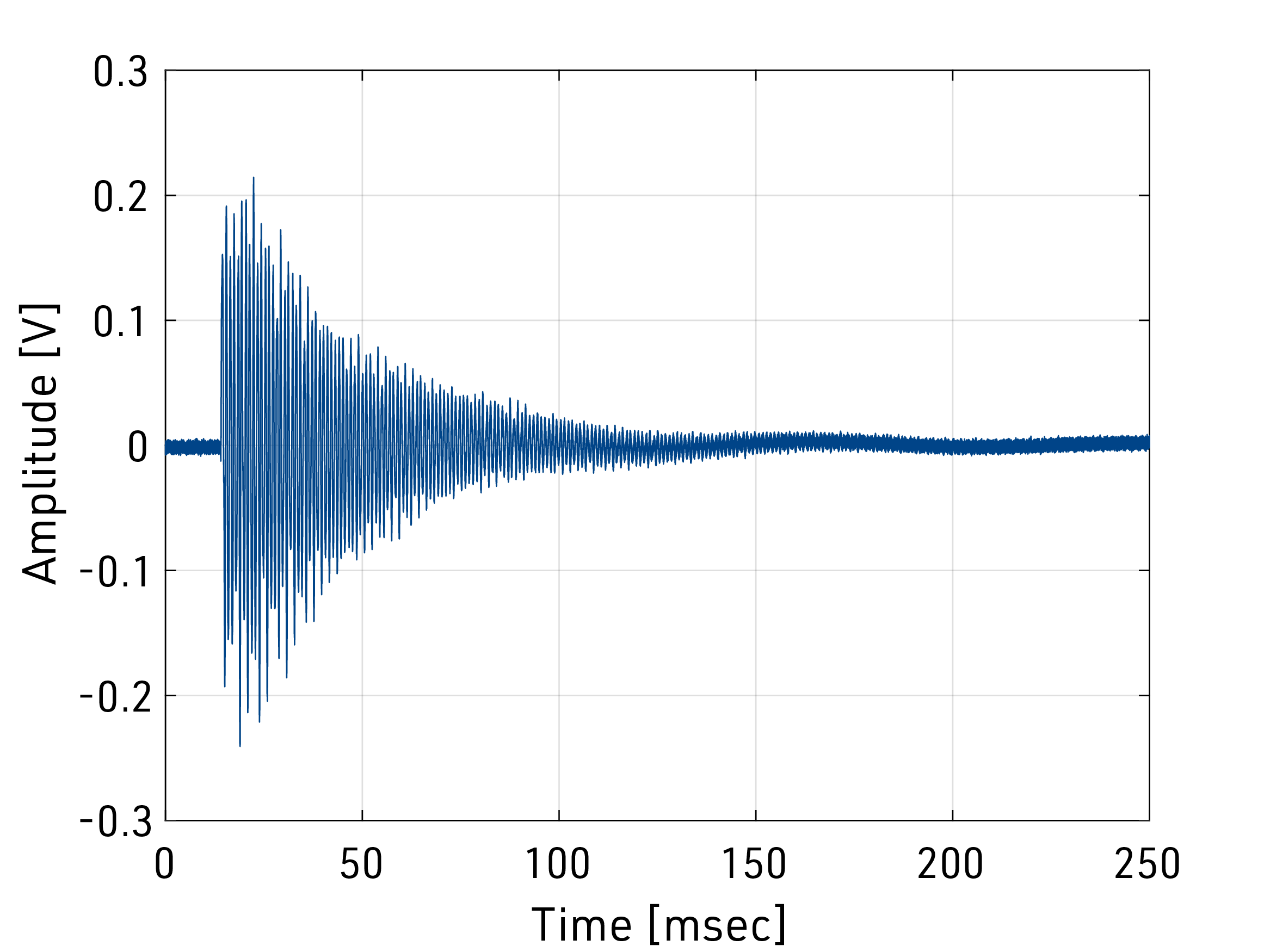
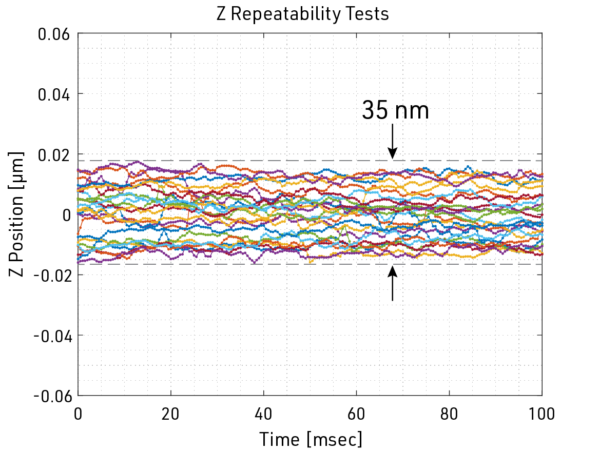 Repeatability test results for the Z degree of freedom. All 25 trials settled within a 35 nm band of each other and didn’t exhibit any substantial drift over a 100 ms period. This measurement period correlates to about five times an average exposure length of the designed-for photolithography process.
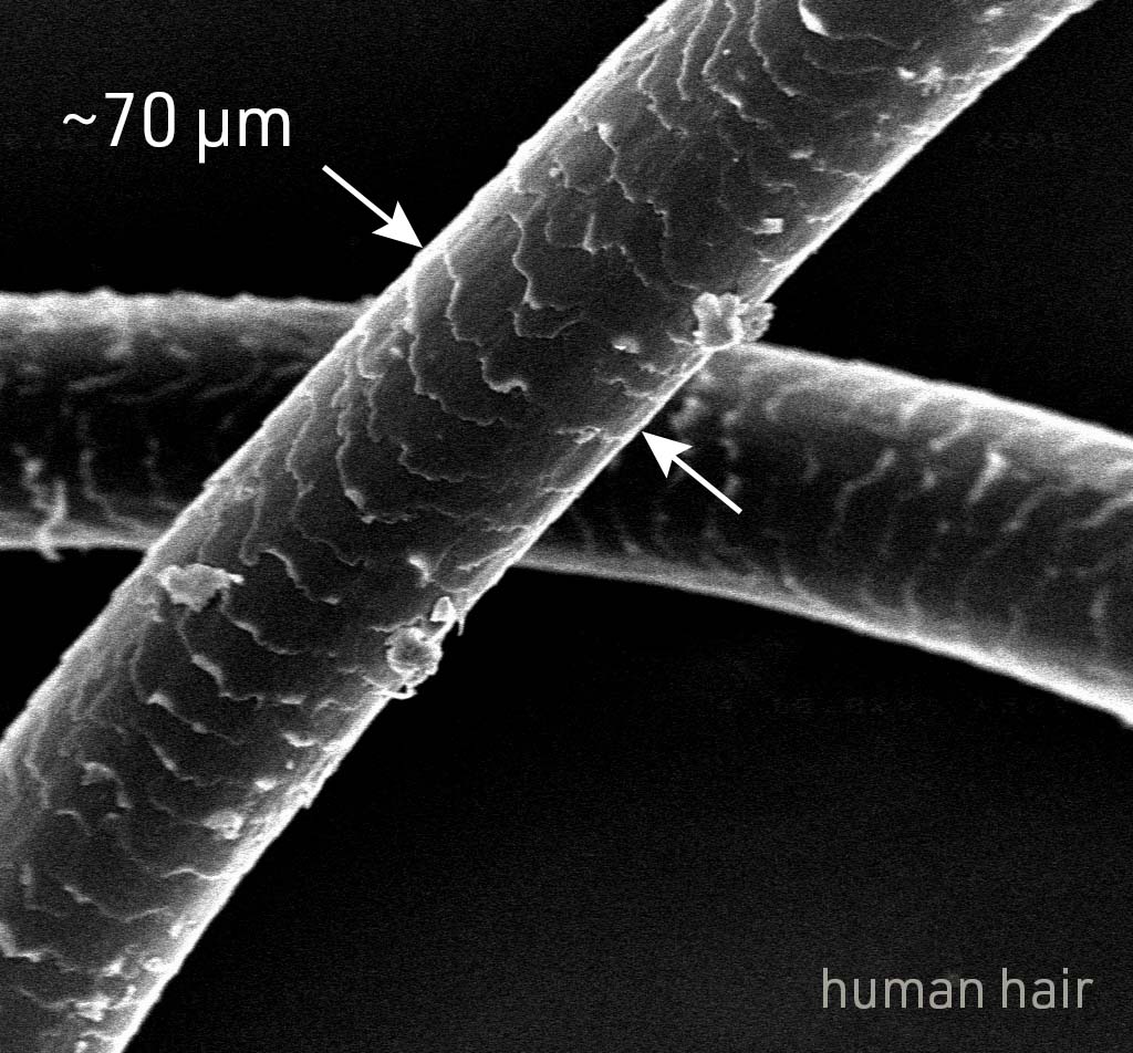 No precision engineering project is complete without the obligatory reference to the thickness of a human hair. On average, a strand of hair is about 70 microns thick, which is over three orders of magnitude larger than the measured Z repeatability of the fine motion stage (0.035 microns).
Electromagnetically Levitated 6 DoF Stage
In parallel to the development of the mechanically-actuated stage, I helped a team of researchers explore an electromagnetically levitated fine motion stage concept. My contribution to this work included the structural design, metrology layout, and fabrication of the protoype machine.
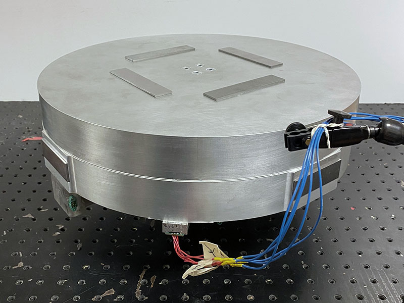
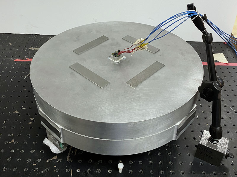
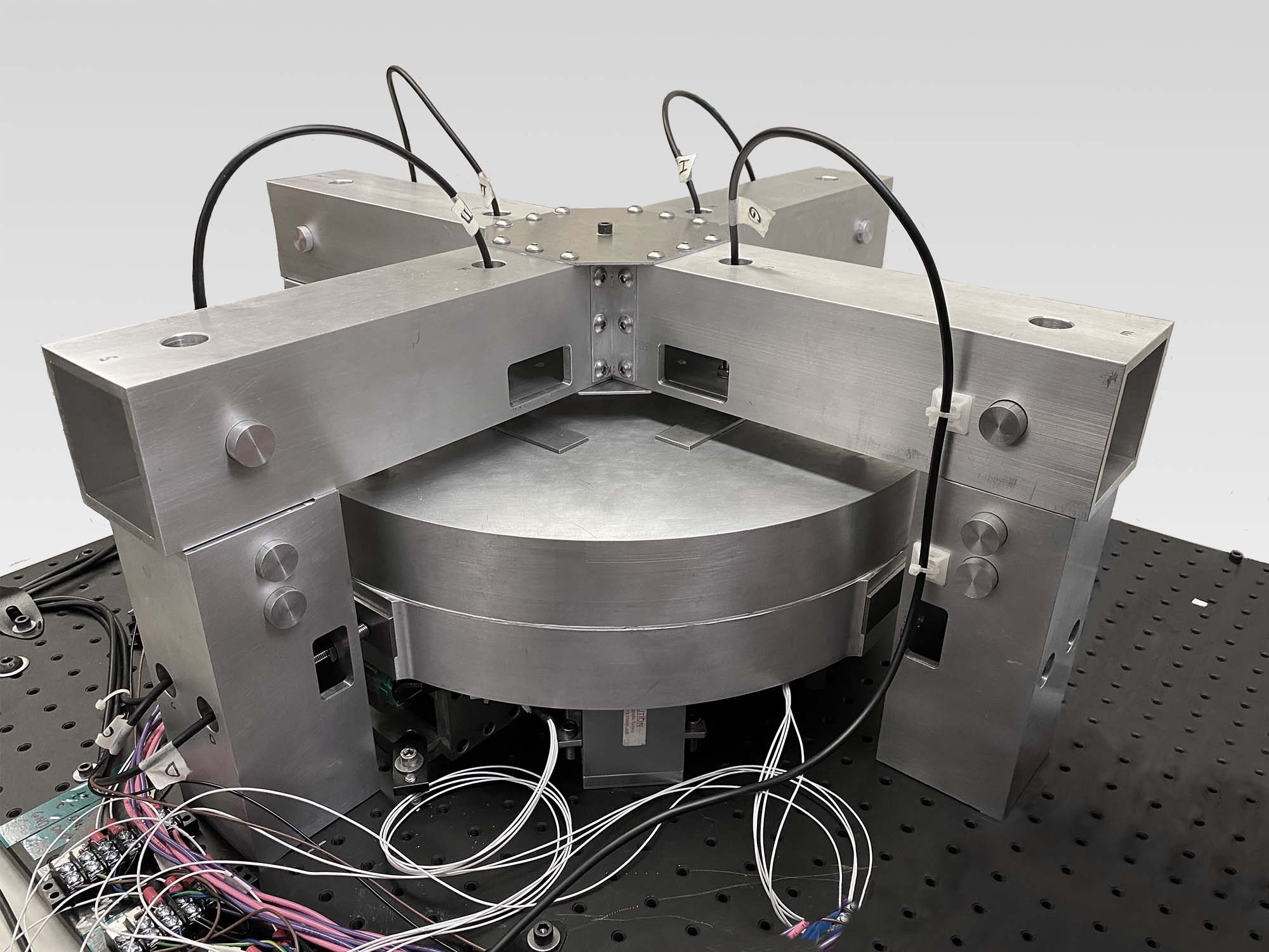 Proof of concept prototype for the levitated stage. A rigid scaffolding around the stage supports inductive sensors that monitor the position and orientation of the 10 kg levitated assembly.
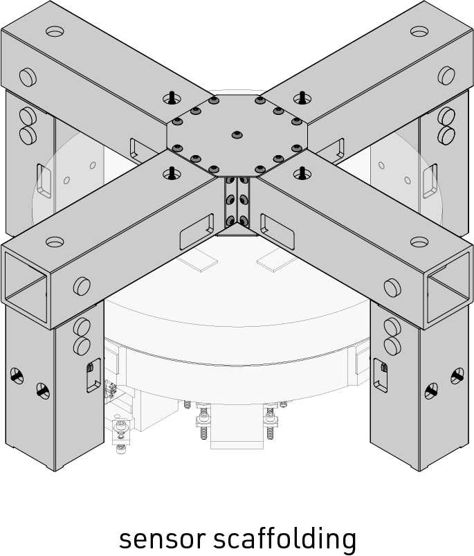 The mechanical design features three main subsystems. The metrology scaffolding is responsible for holding a suite of 8 inductive sensors that are used in tandem to monitor the 6 DoFs of the stage. Oversized aluminum tubing was used to make an ultra stiff, but cost effective structure.
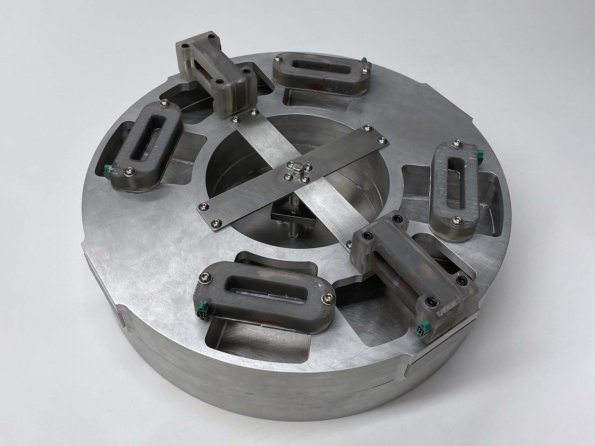
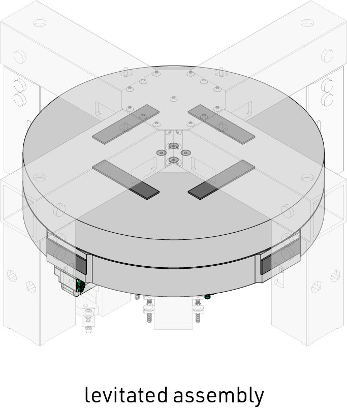 The levitated assembly is the sole moving part of the entire prototype. This structure ties together the coils of electromagnetic actuators as well as sensor targets for the metrology system.
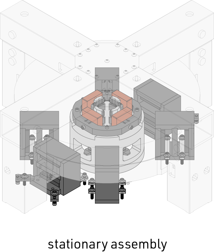 The stationary assembly features all parts that are mounted to the optical table base, which includes back-irons for 6 Lorentz actuators as well as the coils for a two axis flux steering electromagnetic actuator.
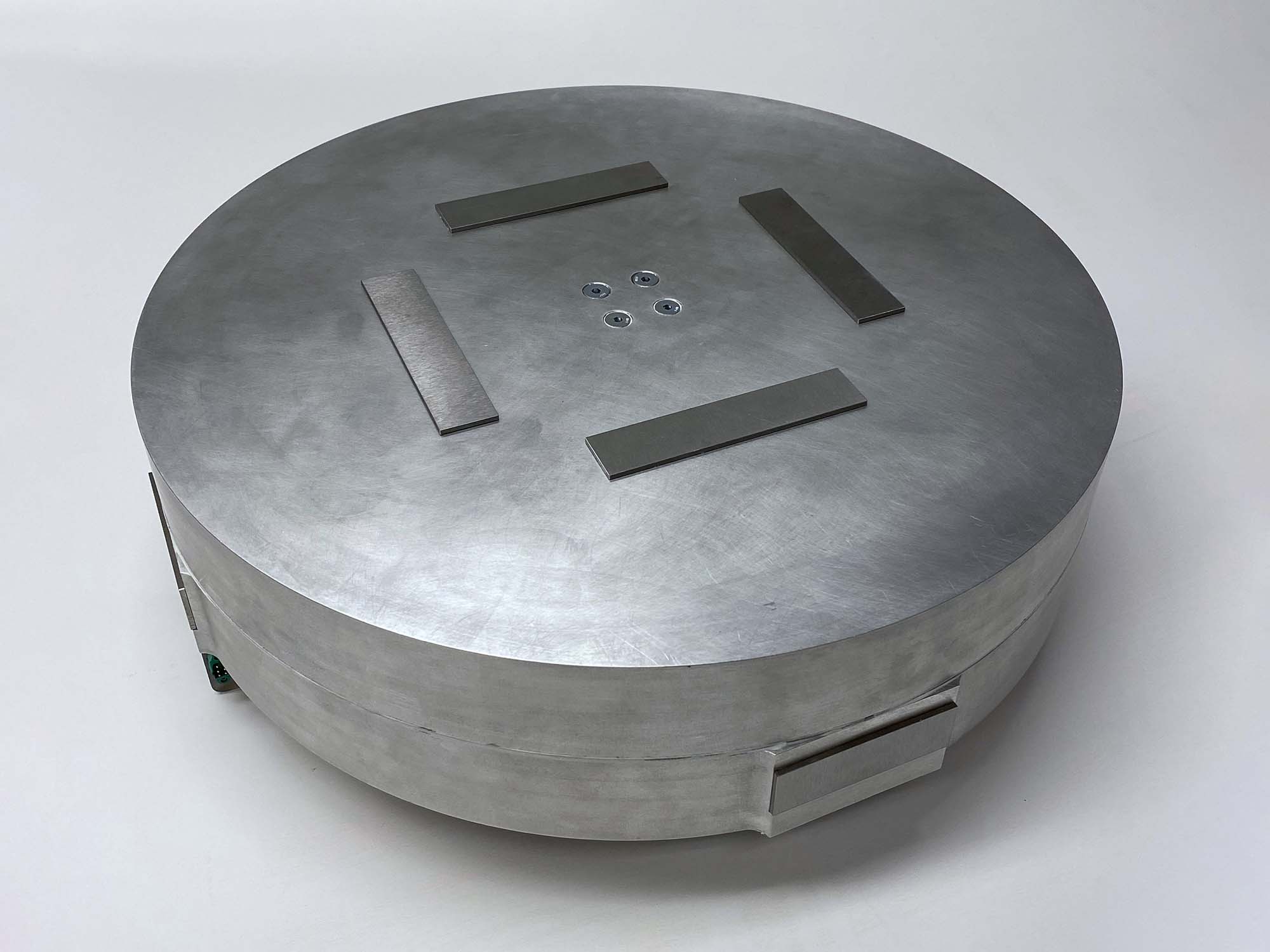
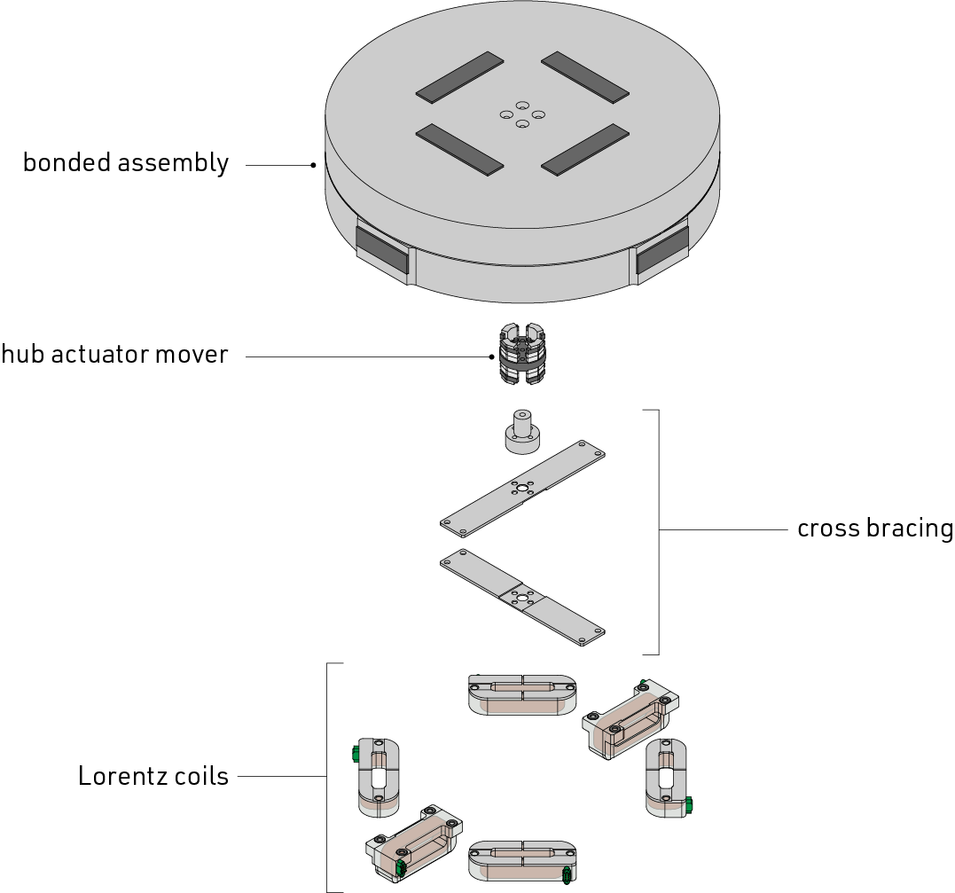 Additional components are bolted to the bonded assembly to complete the levitated assembly. These components include 4 vertically oriented Lorentz coils that levitate the stage and produce θx and θy motion, two laterally oriented Lorentz coils that work together to produce θz motion, the ‘mover’ of the two axis flux steering hub actuator, and additional structural bracing.
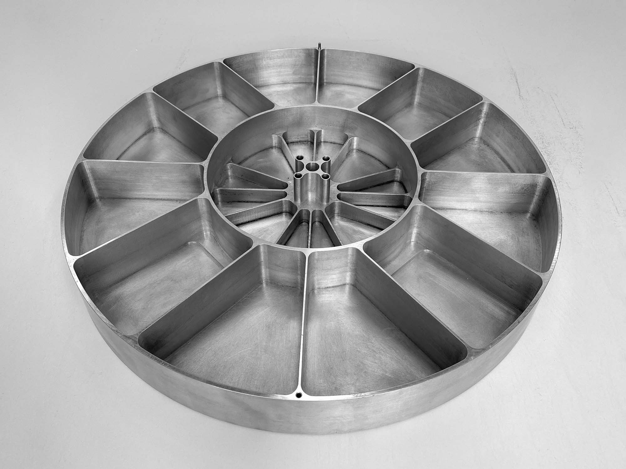
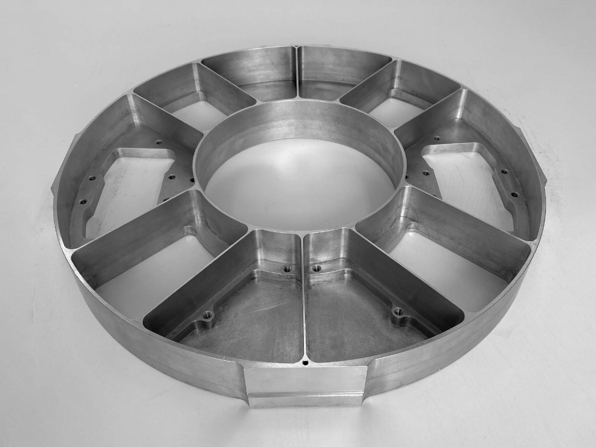
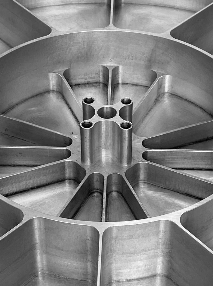
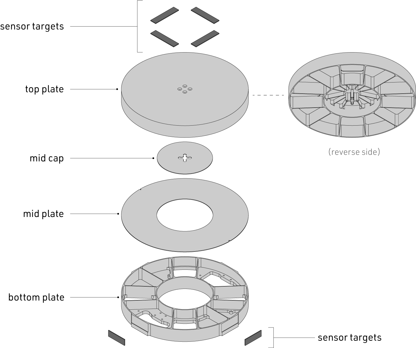 The main component of the levitated assembly is composed of several parts bonded together with structural adhesive. The goal of this structure is to serve as a high stiffness-to-weight ratio chassis for supporting the electromagnetic actuators and sensor targets.
 Detail of the mounting post for the central mover (permanent magnet array) of the 2-axis flux steering actuator.
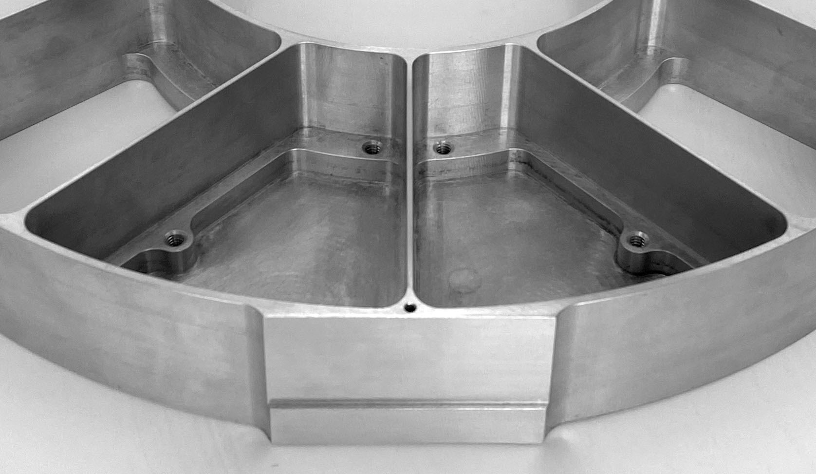 Because MIC-6 tooling plate has a slightly lower yield strength than standard 6061 aluminum, every threaded boss was reinforced with a thicker section of material.
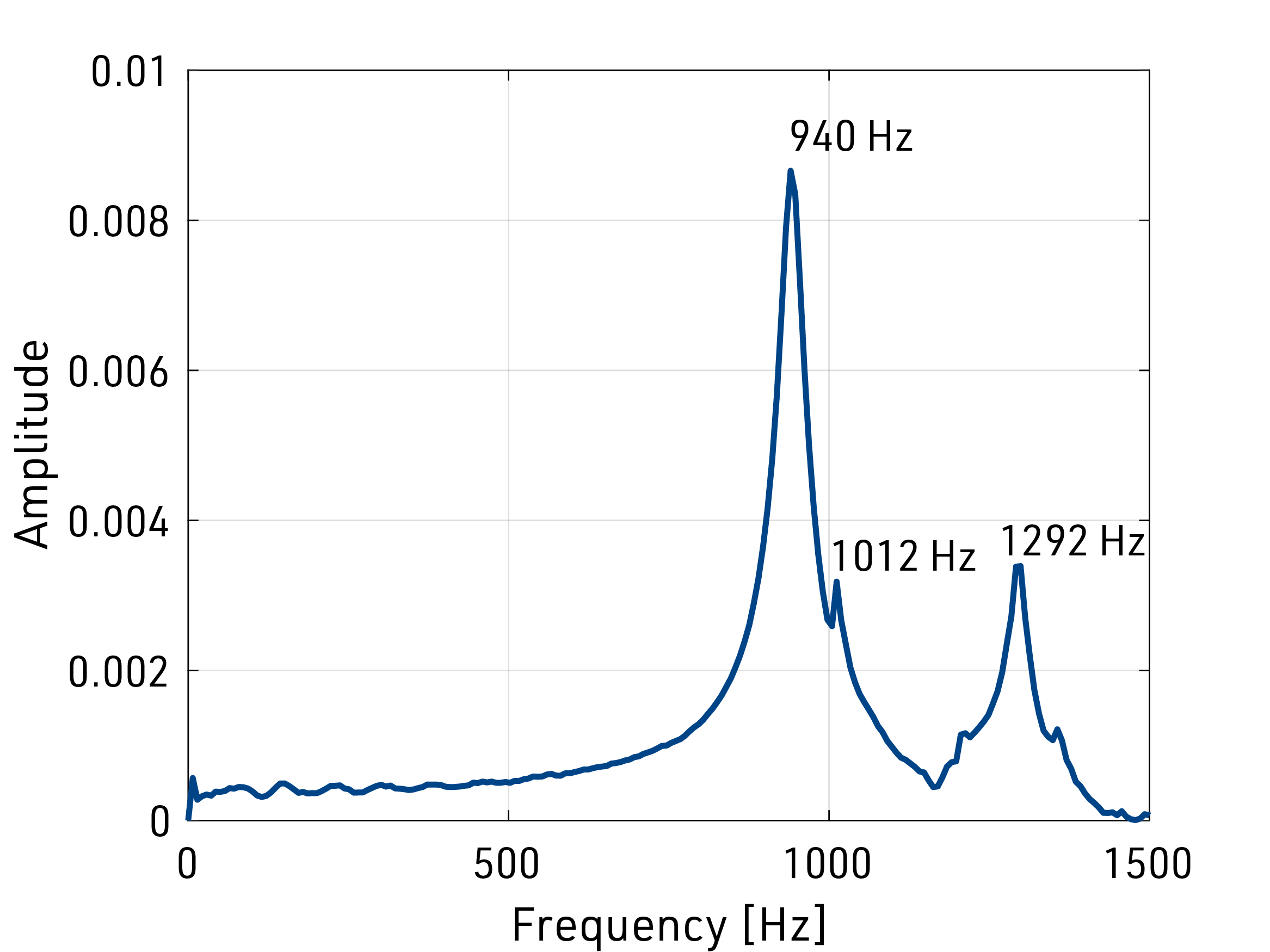
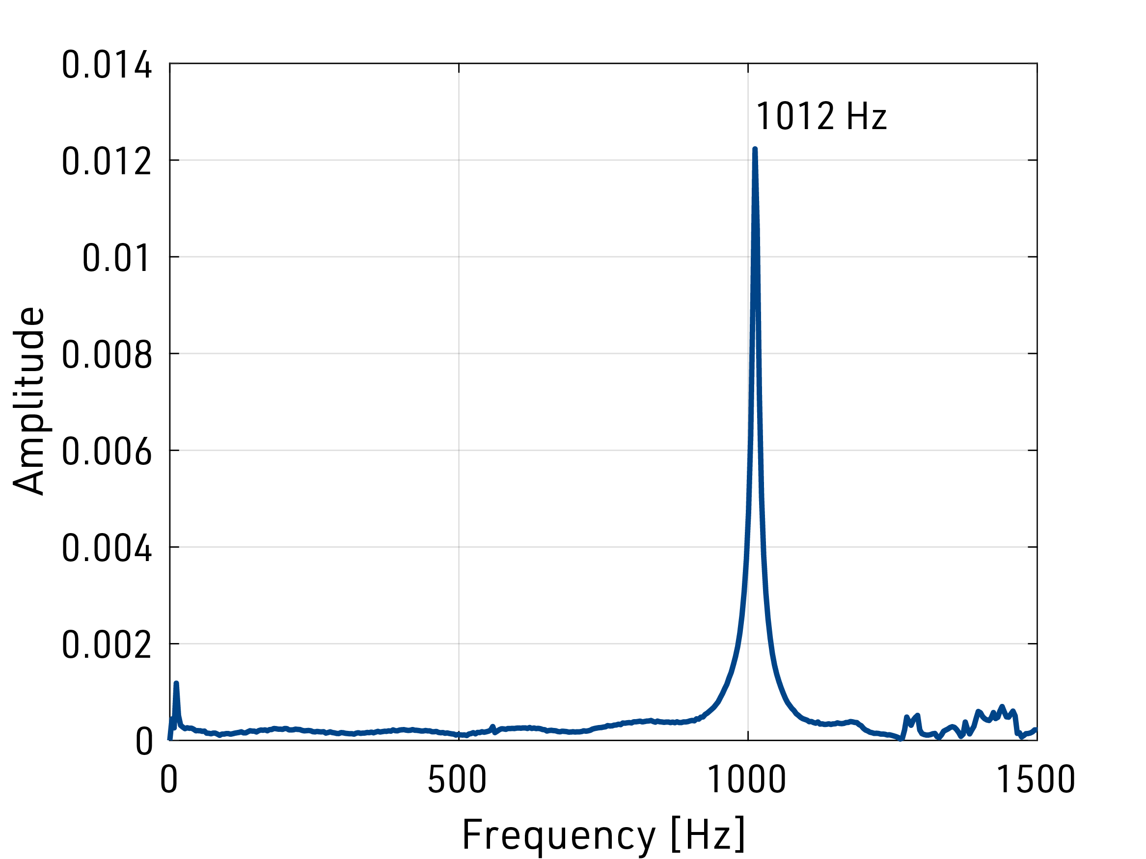
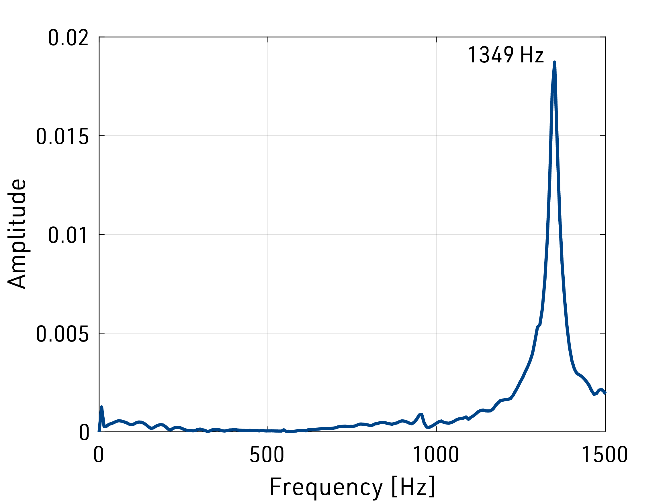
The goal of this prototype was to have a control loop bandwidth of 100 Hz. In order to achieve this with a controller that assumes rigid body dynamics, it was important to keep the resonant modes of the stage at least an order of magnitude above that bandwidth. First principles calculations gave a starting point for the structural design of the stage and full FEA simulations helped to tweak the geometry of components to match the target performance before fabrication.